How to Set A Bounding Box

HOW TO SET A BOUNDING BOX
by Cyndi Richards
I know, first question, what is a bounding box? A bounding box is used to determine what part of the wagon or locomotive is solid. One bounding box cannot pass through another bounding box. It will result in a collision and end of the activity. In MSTS if the bounding box of one car is close to the bounding box of another car a collision will result when these cars are taken through sharp curves or switches. What happens is that one bounding box comes into contact with another bounding box. Note of interest here, if the collision speed is less than the maximum coupling speed, usually 3 mph, the activity will not end.
Before getting to the step by step part I have to put forth some observations and a few tips to make life easier. I am going to show you how I set up a bounding box. Others have their ways, the way that you choose is up to you. The width and the length of the bounding box is set from the central axis of the model. The height is set from the bottom of the bounding box to the top of it. Instead of confusing you with x, y, and z positive and negative offsets, I will put it this way. Total width is determined by placing one half total width on each side of the model centerline. Length is determined the same way. If you know rocket science then the width is x, negative offset is left of centerline, positive offset is to the right. The length is z, negative offset to the rear of centerline, positive offset to the front. y is the height of the bounding box starting at the ground, not the top of the rail. The utility program Bounding Box Editor, available in the file library, is an excellent program. It can also be used to do what we are doing here.
TIPS:
You will be doing a lot of switching back and forth between MSTS and the .sd file you are working on. I do the following. Open the folder of the wagon you are working on, then minimize it. Run the sim to see what adjustments have to be made to the bounding box. Exit the activity back to the Route Selection screen. Press the ALTERNATE and TAB keys. This will minimize MSTS and bring up your wagon folder. Make your adjustments to the .sd file, save and exit, minimize folder. Maximize the sim and click START or press ENTER. Using this procedure, you won’t have to restart the sim every time you make a change.
When the sim is running and your train is on the screen, you have to turn on the BOUNDING BOX DISPLAY. Do this by holding down the CONTROL key and pressing the + on the NUMBER PAD. This sequence will also turn off the display. The red lines in the display will show the outline of the bounding box. To properly
check the length, width, and height you will have to line up the front red indicator line with its rear red indicator line. It takes a light finger on the arrow keys to rotate the camera and get your two lines into one. Using the number two or three view will not give a precise and exact placement setting. However, it will be close enough for our purposes. While I am babbling on here, I’ll tell you why. In the number two and three views the focal point of the camera is on the center of the wagon. While all the other camera parameters can be changed, the focal point cannot.
ABOUT THE SHAPE DEFINITION_< .SD > FILE
When you open the .sd file, the only line we are interested in right now is the last line, as shown below:
ESD_Bounding_Box ( -1.95 0.1 -6.99 1.9 4.96 7.03 )
What do these numbers mean? Thought you would never
ask. Starting from the left, they mean:
-1.95 = distance from the centerline to the left side of the
wagon.
0.1 = the lower height of the bounding box as measured
from the ground.
-6.99 = distance from centerline to rear of wagon.
1.9 = distance from centerline to right side of wagon.
4.96 = the upper height of the bounding box as measured
from the ground.
7.03 = distance from the centerline to front of the wagon.
All numbers represent meters, not yards.
OK LET’S DO IT
STEP 1: Grab a pencil & paper
STEP 2: Open the wagon folder you are going to work on, then
Open the .wag file. Look for this line:
Size ( 3.1m 4.6m 13.32m ) (your numbers will be
different)
Write these numbers down for later. The first number
is the width of the wagon. The second number is the
height of the wagon, and the third number is the
length of the wagon. Close .wag file.
STEP 3: Now run the sim, put your consist on the screen,
turn on the Bounding Box Display and hit 3 key.
As photo # 01 shows, the bounding box is too long
and too high.
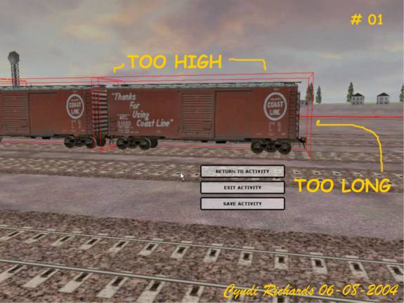
Photo # 02 shows a close up of the bounding box length.
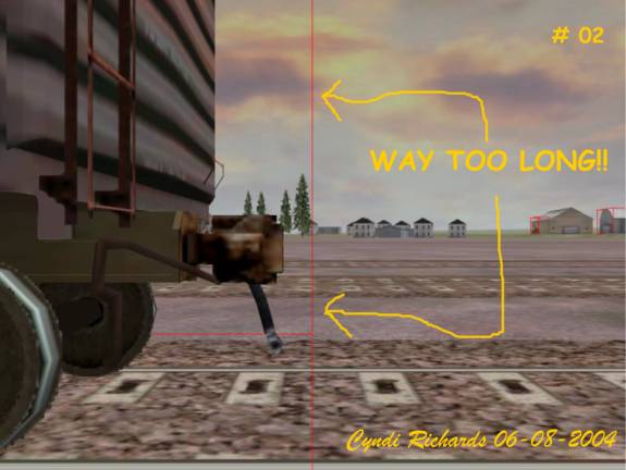
STEP 4: We will start by adjusting the length of the bounding
box. From the numbers you wrote down from the size
line, take the third number and divide it by two.
In the example above the length size was 13.32m
Dividing by 2 gives us 6.66.
STEP 5: Open the .sd file and change the third number to
the result of your division; be sure to retain the
minus sign. Do the same for the sixth number, but
without the minus sign. Using the above example:
Before;
ESD_Bounding_Box ( -1.95 0.1 -6.99 1.9 4.96 7.03 )
After:
ESD_Bounding_Box ( -1.95 0.1 -6.66 1.9 4.96 6.66 )
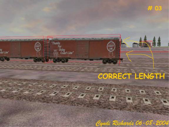
STEP 6: Return to the sim and turn on the bounding box display.
Photo # 03 shows that the box has been shortened.
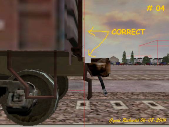
Photo # 04 shows what I consider to be the proper
location for the length. That is at the outer edge
of the draft gear box, also called the coupler
pocket. You will probably have to adjust the numbers
several times to get it in the right place. So always
remember:
INCREASE OR DECREASE THE 3RD & 6TH NUMBERS BY THE SAME
AMOUNT. THEY SHOULD BOTH BE THE SAME NUMBER.
STEP 6: Now that we have the proper length, and you are
feeling rather confident, lets adjust the width.
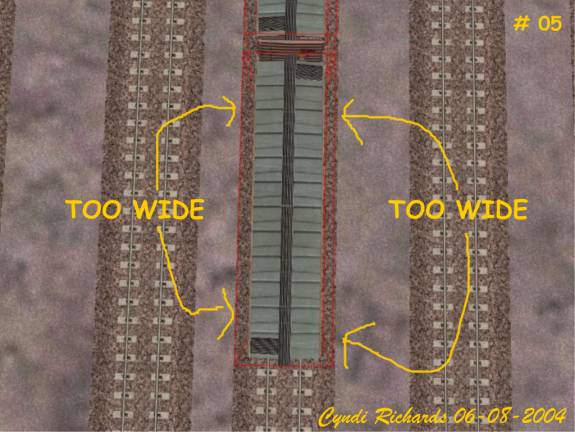
Photo # 05 shows the best view for making any
adjustments to the width which should be along
the outer edge of the sides.
STEP 7: From the numbers you wrote down from the size line,
take the first number and divide it by two. In the
example above the number is 3.1m, dividing by two
gives us 1.55.
STEP 8: Open the .sd file and put the result of your division
In the first and fourth places as shown below.
Before:
ESD_Bounding_Box ( -1.95 0.1 -6.66 1.9 4.96 6.66 )
After:
ESD_Bounding_Box ( -1.55 0.1 -6.66 1.55 4.96 6.66 )
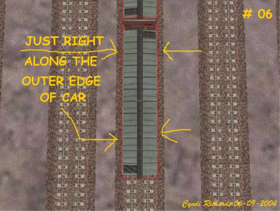
STEP 9: Close the .sd file and run the sim. Photo # 06 shows
a correct bounding box width. Adjust the width as
needed remembering to increase or decrease the
numbers by equal amounts.
STEP 10: Now we are going to adjust the height of the bounding
box, which is the easiest part. At this point I want
to thank Joe Morris and his team of rocket scientists.
Without getting technical on you, let me just state
that as a result of testing, the proper height at
bottom should be 0.9m. This places the bottom of the
box at prototype height. I use this as my standard as
I believe it will be the standard of the future.
So using our sample .sd file, change the second
number to 0.9 as shown below:
Before:
ESD_Bounding_Box ( -1.55 0.1 -6.66 1.55 4.96 6.66 )
After:
ESD_Bounding_Box ( -1.55 0.9 -6.66 1.55 4.96 6.66 )
STEP 11: Now go back to our example size line and look at
the second number which is 4.6m. This is the number
we are going to place in the fifth position of the
.sd file as shown below:
Before:
ESD_Bounding_Box ( -1.55 0.9 -6.66 1.55 4.96 6.66 )
After:
ESD_Bounding_Box ( -1.55 0.9 -6.66 1.55 4.6 6.66 )
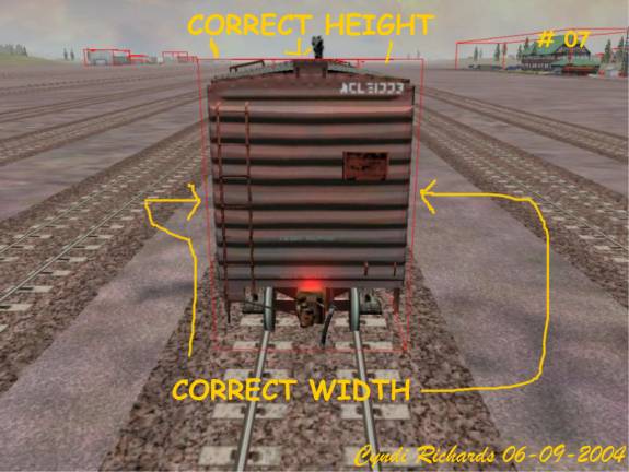
STEP 12: Close the .sd file and start the sim. If you refer back
to photo # 01, you can see the height was too high.
Photo # 07 shows a correct height.
A brief note here on setting the upper height.
On older wagons with a roof walk and vertical brake
wheel, the proper height will be the top of the roof
walk. In the prototype if the brake wheel strikes an
object, it will not normally cause a derailment.
If the wagon has a peaked roof, set the height to
the top line at the top of the peak. Rotating the
camera to end view will be of some help.
STEP 13: CONGRATULATIONS! You have just set up a proper
bounding box.
While I have used a wagon file in this example, the same procedure applies to locomotives.
I hope you have found this guide both informative and easy to use. Again, special thanks to Joe Morris and his team.
Cyndi Richards
BNSFLADY2081@aol.com
[ Home ] | Message Forums | How To Menu ] Copyright © 2004 by Nels Anderson. All Rights Reserved.
Restored from the Train-Sim.Com archive, captured June 19, 2004. About this archive.